Ekofisk 2/4-S Decommissioning Description
A four legged Jacket structure weighing approximately 9447 tonnes in air (incl. piles, grout, marine growth etc.). The Jacket has sixteen piles in total (4 x 4 skirt piles) each of which was cut approximately 2m below the mud line.
Plan
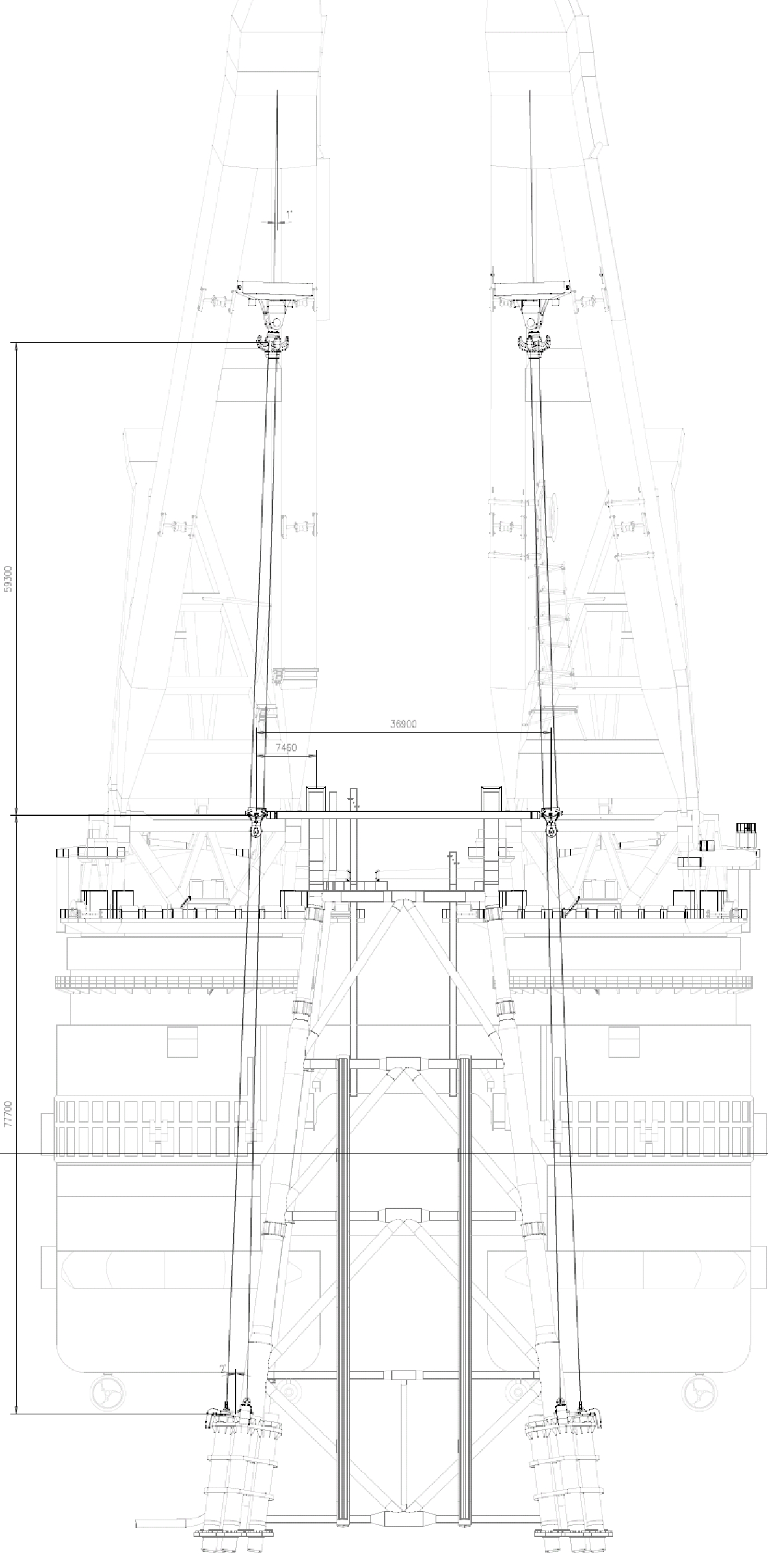
The removal method has the jacket being lifted with the two main hooks via two spreader bars that are connected to the top of the jacket in a restraint frame arrangement; the two spreader bars are then connected in the lower part to the jacket piles with 8 2000t ILTs via 4 slings connecting each to two ILTs. The main activities are as follows:
- Install upper access platform, provide safe access to each leg for make-safe campaign and Nav. aids removal
- Remove nav-aids
- Clear Jacket legs for truss restraint frame
- Remove diagonal bracing above +10.0m
- Cut and Secure Caissons and Riser under restraint truss frames
- Install truss restraint frames
- Secure upper access platform for tow
- Connect rigging to ILTs and to spreader bar onboard deck
- Lift rigging and ILTs overboard and deploy to pile sleeves
- Insert 8 ILTs into 8 piles (2 x ILTs each leg)
- Engage ILTs
- Attach spreader bar to restraint truss with hydraulic clamps/grippers
- Cut remaining 4 x No. piles
- Lift jacket
- Tow jacket
- Set down Jacket at intermediate disposal yard position
- Disengage clamps, ILTs and retrieve rigging
- Remove restraint trusses and install / weld lifting trunnions on top of MSF legs
- Make good or reinforce MSF weld
- Install access platforms / walkways for access to cut line locations
- Cut jacket top section
- Install lift rigging
- Lift jacket upper section and tow to disposal yard
- Set down on quayside
- De-rig and transit to lower section
- Re-rig for lower section lift
- Install ILTs in the same piles used before, lift and tow to disposal yard
- Set down in front of quay and de-rig
ILT Idealization
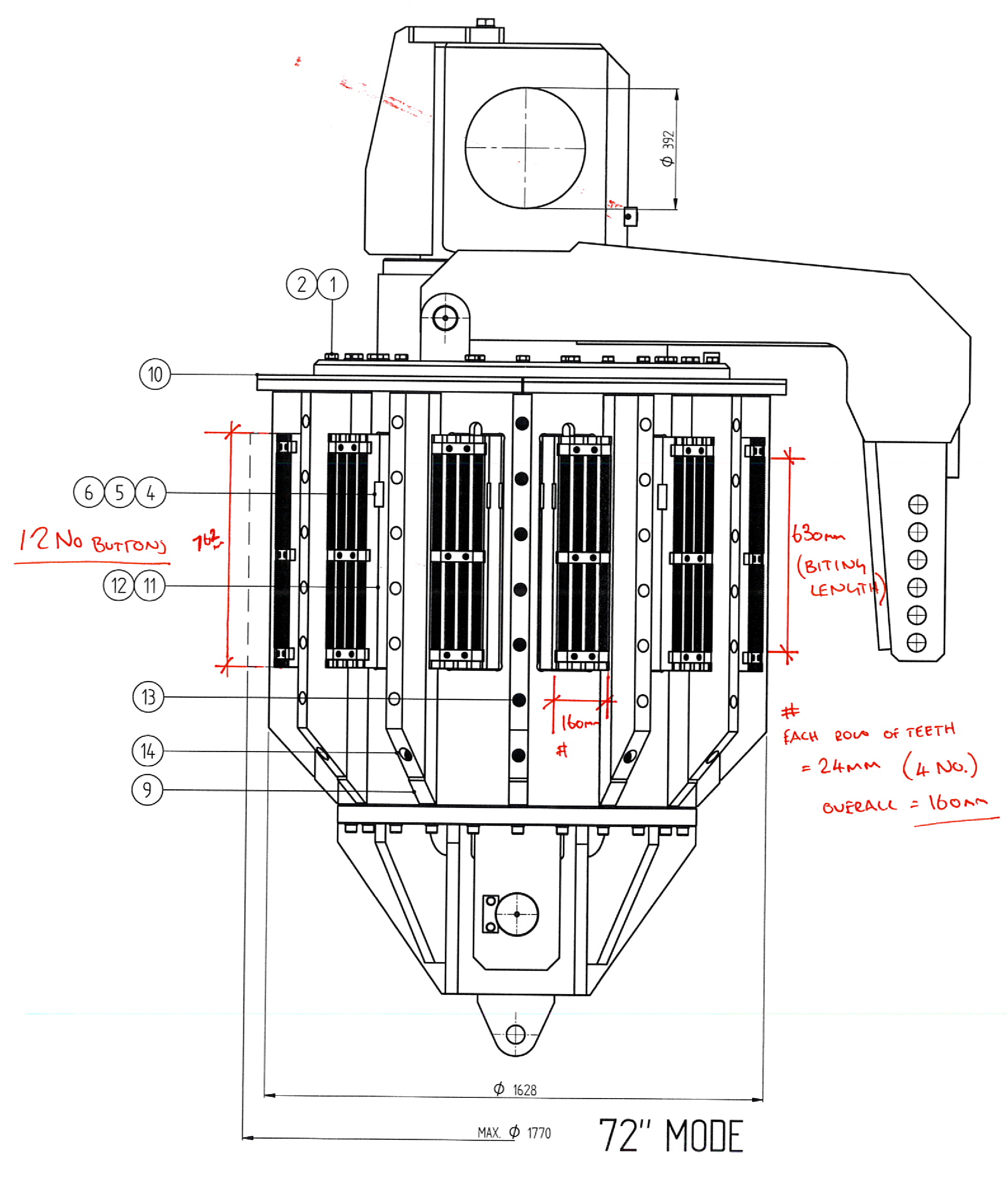
The ILT device is modeled with 13 rigid bodies, a center mandrel and 12 wedges. By using the penalty contact model, the actuation of the wedges by the $9^\circ$ conical surface from the axial load is possible by using frictionless contact between the mandrel and the wedges along the conical surfaces. Each wedge has a 630 mm x 160 mm contact patch. The assumed coefficient of friction between the contact patch and the pile ID is assumed to be a relatively low 0.3.
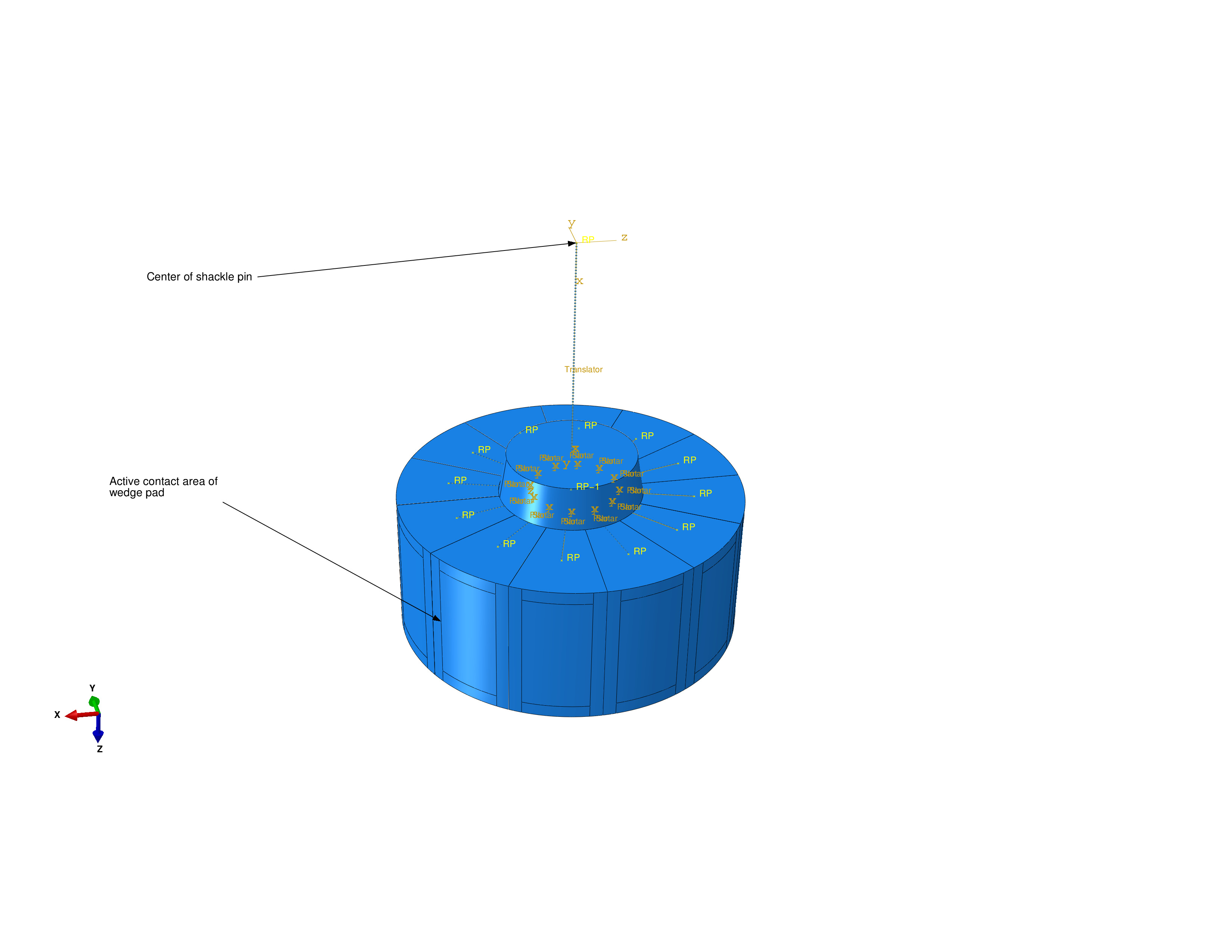
In addition to the contact between the central mandrel and the wedges, the actuation is controlled by three types of connector elements:
- The translator connector between the reference node at the center of the shackle pin ($RF_1$) to the reference node at the center of the wedge group constrains the wedge group reference node ($RF_2$) to remain on a line defined by the position and rotation of $RF_1$.
- The planar connections from the wedge group reference node ($RF_2$) to the wedge reference nodes ($RF_3^n$) constrains $RF_3^n$ to remain on a plane defined by the position and rotation of $RF_2$.
- The slot connectors from the wedge group reference node ($RF_2$) to the wedge reference nodes ($RF_3^n$) constrains $RF_3^n$ to remain on a line defined by the position and rotation of $RF_2$. Thus the wedges can radially expand.
Results
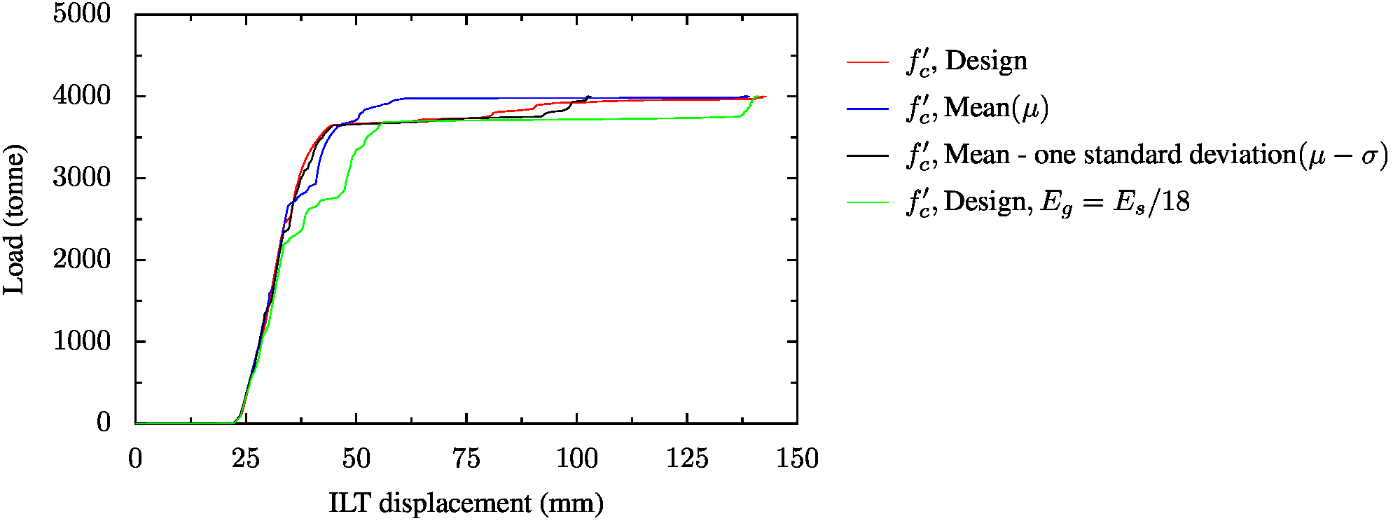
The parameters of the grout concrete damaged plasticity model were varied based on design compressive strength, compressive and tensile strength from tests, and assumed elastic modulus (see Calculation of grout elastic modulus and Statistical analysis of grout test data). The results indicate that ultimate capacity of the pile/sleeve joint is controlled by the pile. The displacement at which the ultimate capacity is reached is smaller for higher strength and stiffer grouts. The load at which the force versus displacement curve becomes non-linear due to grout crushing and cracking is approximately the same for all of the models.
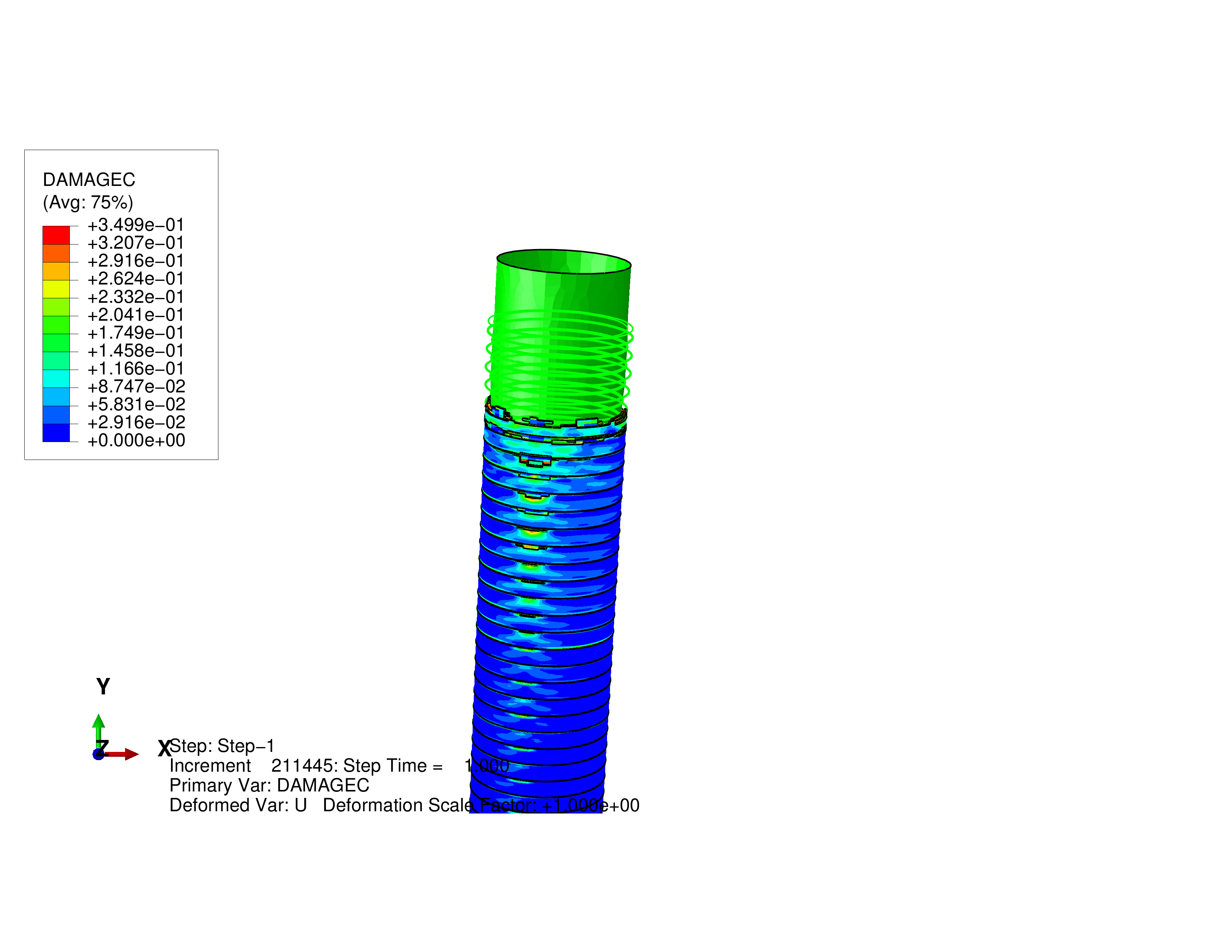
Grout damage
Significant grout crushing occurs at the ILT beyond 3500 tonne. Below the ILT, the only damage occurs due to tensile cracking in the vicinity of the shear beads. This damage is expected and does not effect the shear transfer from the pile to the sleeve.