Finger-type Slug Catcher CFD Analysis
CFD calculations have been used to determine the best header layout for a finger type slug catcher, so as to evenly distribute the flows over the different fingers. Downstream of the header the two-phase flow in the finger pipe of a finger-type slug catcher can be analyzed using CFD techniques. When the fluid flow in the inlet header manifold is evenly distributed among the different fingers, it is necessary to obtain stratified flow to promote liquid separation. The two-phase flow in the separation section is simulated to study the amount of liquid at the intersection with and through the gas riser, which is critical in flow assurance. Problems typically occur when velocities become too high and the flow is too turbulent. This could result in gas carrying liquid from the storage section back through the gas riser.
Finger-type Slug Catcher CFD Analysis
The CFD analysis attempts to predict two aspects of the operation when a slug is received:
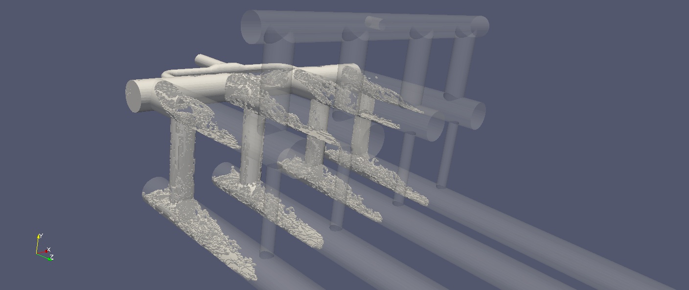
- The flow dispersion to the fingers with the ability to model the "manometer" effect when different fingers receive a greater flow rate than other branches.
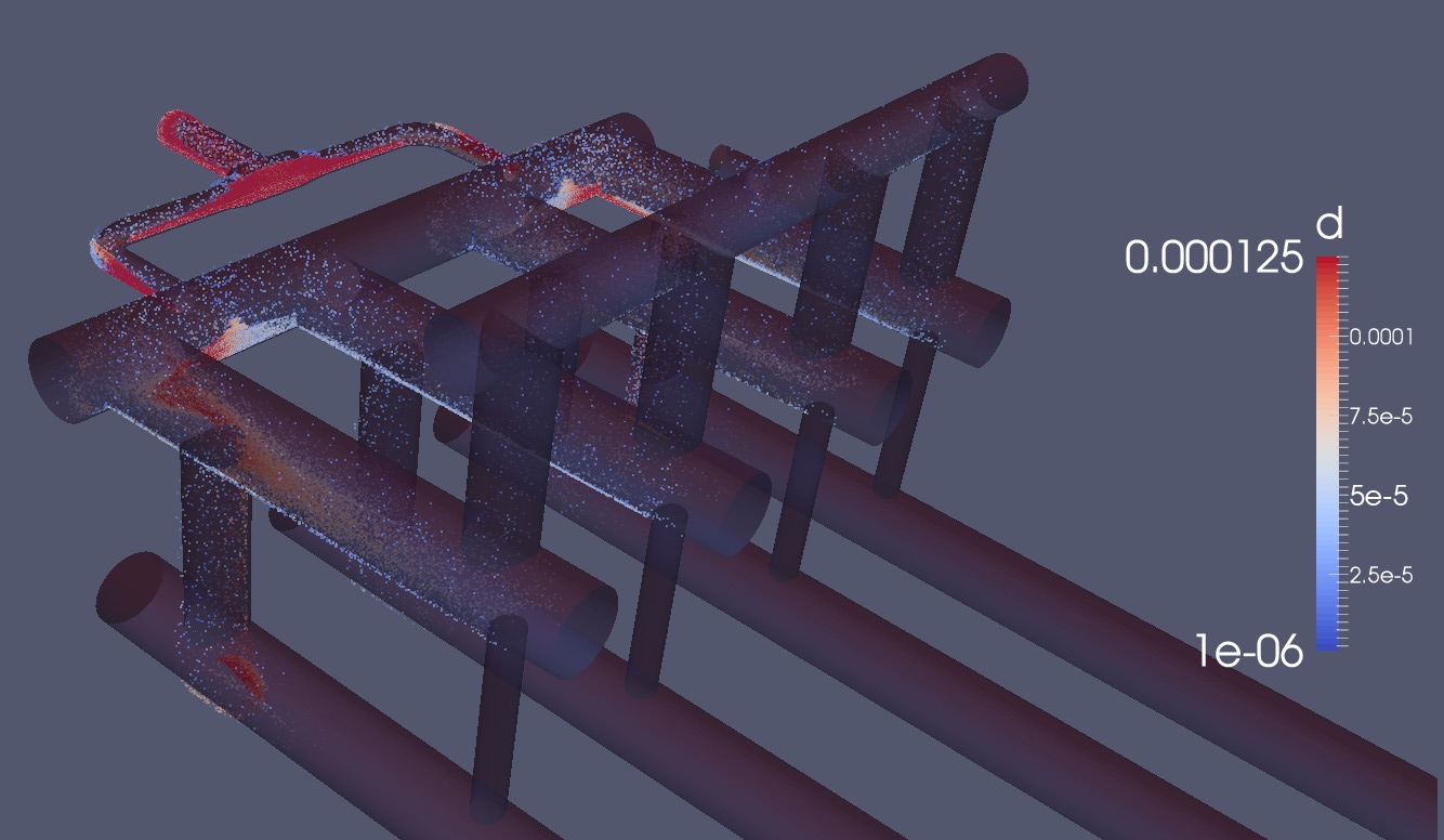
- A statistical description of the liquid droplet size at the outlet. A discrete element method (DEM) is used for computing the motion and effect of a large number of small particles. Particles are injected into the inlet at an initial velocity of 4.2 m/s with the diameter calculated according to a normal distribution with an expected mean of $125 \mu \mathrm{m}$, a maximum diameter of $250 \mu \mathrm{m}$, and a minimum diameter of $1 \mu \mathrm{m}$. The motion of the particles is controlled by the previously calculated steady state turbulent flow, sphere drag, gravity, and Saffman-Mei lift force.